DC Blocks in Modern RF Labs
Leave a message
In RF labs and production lines, DC blocks are one of those small parts that quietly protect your most expensive hardware. In practice they are coaxial modules that use a capacitor to block DC and very low frequency content, while allowing RF signals to pass with minimal impact.
That simple function becomes critical once you start working with wideband receivers, bias networks, high power drivers or unknown customer fixtures. A well-chosen DC block can be the difference between a clean measurement and a damaged test port.
What A DC Block Does
At a circuit level, a DC block is a passive coaxial component with a capacitor placed in series in the RF path. That series capacitor behaves like a controlled high pass element:
- It prevents DC and audio frequency currents from flowing through the line
- It passes RF energy across a specified operating band, from kHz or MHz up to many GHz
- It helps to protect sensitive RF front ends and instrument ports from DC bias or transient events
- It can improve signal to noise ratio and dynamic range by removing unwanted DC offsets and ground loop currents in the system
Common use cases include VNAs and spectrum analyzers, signal sources with built in modulation, wideband receivers, and communication links where one side carries DC bias that must not reach the other side.
Inner, outer and inner/outer configurations
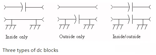
Most coaxial DC blocks in the industry follow three well defined configurations.
Inner DC block
- The capacitor is in series with the center conductor of the coax.
- DC is blocked on the signal conductor, while the outer conductor stays at DC ground.
- Typical uses:
Protecting analyzer or receiver inputs from DC on the line
Coupling a high frequency signal into a node that already has its own DC bias
Reducing DC offsets that would otherwise compress the dynamic range of a measurement
Outer DC block
- The capacitor is in series with the outer conductor (shield).
- DC and low frequency currents are blocked on the shield, while the center conductor stays electrically continuous at DC.
- Typical uses:
Breaking ground loops between different racks or chassis
Preventing DC or surge currents from flowing along the shield into sensitive equipment
Reducing interference that rides on the outer conductor
Inner / outer DC block
- Capacitors are placed in series with both inner and outer conductors.
- This provides full DC isolation between the two sides of the connection.
- It is used when there are significant ground potential differences, or when you need both signal and shield to be DC isolated while still carrying RF.
These three configurations are standard across many catalog vendors, which makes it easier for engineers and buyers to speak the same language when specifying parts.
The specs that matter in real projects
For both engineers and procurement teams, a few parameters decide whether a DC block is a good fit for a design or test bench.
Frequency range
- The operating band must comfortably cover your use case, not only a single headline number.
- On the market you will see inner DC blocks in connector families like SMA, N, 2.92 mm and 1.85 mm spanning from a few kHz or tens of MHz up to 18 GHz, 26.5 GHz, 40 GHz or even 67 GHz.
- Wideband coverage reduces how often you need to swap hardware when you change setups.
01
Insertion loss
- Good DC blocks add as little loss as practical, often on the order of a fraction of a dB within most of their band.
- In precision test systems every dB in the budget matters, especially when there are multiple adapters, cables and fixtures in series.
02
Return loss and VSWR
- A well-designed DC block keeps the line well matched over its usable frequency range.
- Typical catalog parts specify low VSWR so that reflections are small and the measurement uncertainty stays under control, even at mmWave frequencies.
03
Voltage and power rating
- The DC rating tells you how much DC bias or transient the block can withstand without breakdown.
- In practice, many families offer options in the roughly 30 V to 100 V range, which covers a lot of laboratory and system level use cases.
- For system designers this is often a go or no-go parameter.
04
Mechanical construction
- Stainless steel bodies with precision interfaces are common for high frequency parts, since they support repeatable mating, good environmental robustness and many connect or disconnect cycles in the lab.
- For production lines, having the same mechanical style across different connector series simplifies fixturing and documentation.
05
Flexi RF DC blocks
From kHz benches to 110 GHz mmWave
At Flexi RF, we build DC blocks around these exact trade offs: wide frequency coverage, clean RF performance and robust mechanical design.
Today our portfolio covers several key connector series that lab and system engineers use every day:
1.0 mm inner DC block
- Part number FR5-GDCB-110G-10-JK
- 1.0 mm male to 1.0 mm female
- Operating frequency: 300 kHz to 110 GHz
- Rated voltage: 30 V
- Stainless steel body, designed for low insertion loss and controlled VSWR
- Targeted at applications where you need true mmWave performance while still protecting extremely sensitive front ends and extenders
01
1.85 mm inner DC block
- 1.85 mm male to 1.85 mm female
- Operating from 10 MHz to 67 GHz, 50 Ω impedance, stainless steel body
- Rated for 60 V DC, with low insertion loss and a tight VSWR specification
- Used heavily in 67 GHz test and measurement setups and high frequency communication R&D
02
2.92 mm inner DC block
- 2.92 mm male to 2.92 mm female
- Operating from 10 MHz to 40 GHz, 50 Ω impedance, stainless steel
- Designed with low insertion loss and very good matching across the band
- A practical choice for 26.5 GHz and 40 GHz benches and for 5G sub systems
03
SMA inner DC block
- SMA male to SMA female
- Operating from 10 MHz to 18 GHz and 30 MHz to 27 GHz, stainless steel body
- Optimized for low insertion loss and good VSWR for classic L band to Ku band test setups
04
N type DC blocks
- N male to N female configurations that support low frequency starts down to 100 MHz and go up to 18 GHz, with DC ratings around 100 V depending on the exact model
- Well suited to rugged environments and power carrying lines where you still need DC isolation
05
Across these connector series, the goal is consistent: give engineers a family of DC blocks that they can treat as part of the core RF infrastructure instead of one-off accessories. By keeping the construction, plating and RF design aligned, the same part numbers can live comfortably in
metrology labs, production testers and deployed systems.
For buyers, that consistency also means fewer surprises. The same design principles apply whether you are sourcing a handful of 1.0 mm blocks for a mmWave bench or standardizing on SMA and N type blocks across multiple lines.
Typical application patterns
Test and measurement
- Protect VNAs, spectrum analyzers and receivers from unknown DC content coming from customer boards or fixtures.
- Isolate different parts of a system during troubleshooting so that ground potential differences and DC offsets do not mask RF issues.
- Build reusable fixtures where only the DUT (Device Under Test) changes and DC blocks absorb the "unknowns" on the line.
RF communication and mmWave R&D
- Insert DC blocks between active front ends and shared test infrastructure to protect expensive converters, LNAs and drivers.
- Use wideband 1.85 mm and 1.0 mm DC blocks when characterizing components and subsystems up to 67 GHz and 110 GHz.
Industrial and mission critical systems
- Prevent unwanted DC or low frequency currents from traveling along long coax runs in factories and outdoor installations.
- Break shield related ground loops in systems that mix sensitive receivers, high power drivers and control electronics.
- In all these scenarios, the right DC block quietly increases safety margins, improves measurement repeatability and reduces downtime.
Closing thought
DC blocks may look like simple adapters, but in modern RF systems they are strategic components. They protect high value hardware, clean up difficult measurements and give designers more freedom in how they bias and reference their circuits.
If you are putting together a new test bench or integrating a high frequency subsystem and want to make sure the DC side is under control from 300 kHz all the way up to 110 GHz, our team at Flexi RF and is happy to help you choose the right combination of connector type, frequency range and voltage rating for your setup.