A Comparative Analysis Of Applications: T-type Biasers Vs. DC Blocks
Leave a message


Both T-type biasers and DC blocks are key components in radio frequency (RF)/microwave systems that handle the relationship between DC and RF signals, but they differ significantly in terms of their functional positioning and application scenarios. The following is a detailed comparison from aspects such as core functions, working principles, application scenarios, and performance characteristics:
I. Core Functions and Positioning
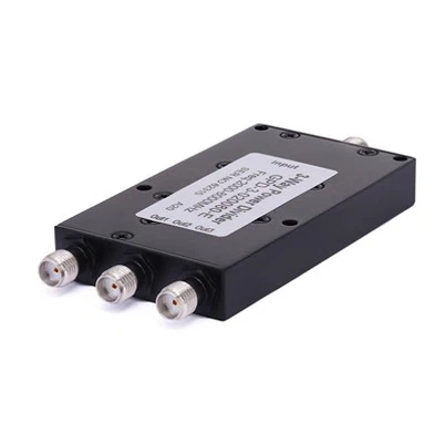
Tee Biaser
Its core function is to simultaneously realize RF signal transmission and DC bias injection. That is, it provides DC operating voltage/current for active devices (such as amplifiers and transistors) without interfering with RF signal transmission. It is a composite device integrating "RF transmission + bias supply".
DC Block
Its core function is to simply block DC or low-frequency signals and only allow RF/microwave signals to pass through. It is not involved in bias supply and is only used to isolate DC interference.
II. Comparison of Working Principles
|
Device
|
Number of Ports
|
Core Structure
|
Working Logic
|
|
| T-type Biaser | 3 (RF IN, RF OUT, DC IN) |
Consists of 2 DC-blocking capacitors (C1, C2) and 1 RF choke inductor (L1) |
- RF signals: Transmitted between RF IN and RF OUT via C1 and C2 (capacitors allow high-frequency signals to pass); |
|
| - DC bias: Applied to the RF link from DC IN through L1 (the inductor blocks RF from entering the DC port while allowing DC to pass). | ||||
| DC Block | 2 (IN, OUT) | Core is a DC-blocking capacitor (or a high-pass filter structure with capacitor + inductor compensation) | - DC signals: Capacitors exhibit infinite impedance to DC (0Hz), completely blocking them; | |
| - RF signals: Capacitors exhibit low impedance to high frequencies, allowing RF signals to pass. |
III. Comparison of Application Scenarios
Typical Applications of T-type Biasers
Power supply for active devices: Providing DC bias for active devices such as RF amplifiers, mixers, and PIN diodes. For example:
In RF power amplifiers, it is necessary to apply DC voltage to the gate/drain of the power amplifier tube while allowing RF signals to pass through. The T-type biaser can achieve both simultaneously, preventing DC from interfering with RF signals.
In phase shifters of phased array radars, DC is required to control the phase-shifting state while transmitting RF signals. The T-type biaser can separate the control DC from the RF signals.
Links requiring coexistence of "RF + DC": In RF testing, when applying DC bias to the DUT (Device Under Test) while inputting RF signals, the T-type biaser is used to realize the "confluence" of signals and bias.
Typical Applications of DC Blocks
Blocking DC interference: When there is a DC potential difference between the front and rear stages in the RF link, DC is isolated to avoid mutual influence. For example:
The DC bias voltage of the front-stage device may interfere with the operating point of the rear stage. A series DC block can block DC and only allow RF signals to transmit.
There may be DC generated by static electricity in the antenna feeder. The DC block can block the DC to protect the backend receiver.
Isolating low-frequency components: In scenarios where pure RF signals need to be extracted (such as spectrum analysis), the DC block can filter out DC or low-frequency drift components in the signal to ensure measurement accuracy
IV. Comparison of Performance Parameters
|
Parameter
|
Focus for T-type Biaser
|
Focus for DC Block
|
|
|
Insertion Loss
|
Loss during RF signal transmission (needs to consider the impact of the bias structure on RF) |
Loss during RF signal transmission (mainly depends on the high-frequency performance of the DC-blocking capacitor) |
|
| DC Handling Capability | Maximum DC voltage/current (must match the power supply requirements of active devices) | None (only needs to block DC, no involvement in transmission) | |
| RF Isolation | Isolation of RF signals from the DC port (to prevent RF leakage into the power supply) | None (only needs to block DC, no involvement in RF isolation) | |
| DC Isolation | Isolation of DC from the RF input/output ports (to prevent DC leakage) | DC blocking capability (typically requiring a DC impedance > 10kΩ) | |
| Voltage Standing Wave Ratio (VSWR) | Requires good matching at both RF ports and the bias port | Only needs to ensure good matching at the RF ports |
Selection criteria: If power supply to the device and RF signal transmission are both required, a T-type biaser should be chosen; if only DC blocking is needed (without power supply), a DC block is appropriate. The two can be used in conjunction (for example, first powering the device via a T-type biaser, then using a DC block to intercept excess DC).