How to test the S-parameters for a RF amplifier?
Leave a message

Testing the S-parameters of an RF amplifier is a core process for characterizing its performance, as it can fully reflect key indicators such as the amplifier's input-output matching characteristics, gain performance, isolation, and stability within the operating frequency range. The following is a detailed procedural guide for this test, including key considerations and descriptions of required equipment.
I. Core S-parameters to be tested for RF amplifiers
For a two-port RF amplifier, the S-parameters that need to be focused on include:
S₁₁ (Input Reflection Coefficient): Indicates the degree of matching between the amplifier and the source impedance (typically 50Ω);
S₂₁ (Forward Transmission Coefficient): Represents the gain of the amplifier, i.e., the ratio of output power to input power;
S₁₂ (Reverse Transmission Coefficient): Reflects the isolation, which is the amount of signal leaking from the output end to the input end;
S₂₂ (Output Reflection Coefficient): Shows the matching degree between the amplifier and the load impedance (usually 50Ω).
II. Required equipment and test accessories
To accurately measure S-parameters, the following equipment is needed:
Vector Network Analyzer (VNA): The core instrument, used to generate swept-frequency RF signals, measure the amplitude and phase of reflected/transmitted signals, and calculate S-parameters.
Calibration Kit: Typically a SOLT (Short, Open, Load, Thru) kit, used to calibrate the VNA and eliminate errors caused by cables, connectors, and test fixtures.
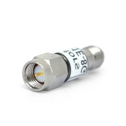
RF Cables and Connectors: Low-loss, high-quality coaxial cables whose impedance must match the system (standard is 50Ω) to reduce signal loss and reflection.
Bias Tee (Optional): A passive component used to combine DC bias (for powering the amplifier) with RF signals, ensuring that DC does not enter the RF ports of the VNA.
Attenuator (Optional): If the output power of the amplifier is high, a fixed attenuator can be installed at the output port to protect the VNA's receiver from overload.
Load (Optional): A 50Ω termination load, used for stability testing or verifying output matching.
III. Step-by-step test procedure
1: Prepare the amplifier and test environment
Clarify the amplifier specifications: Its operating frequency range, input/output power limits, DC bias requirements (voltage/current), and linear range (to avoid entering saturation during testing).
Power the amplifier: Use a stable DC power supply to provide the required bias voltage/current.
2: Calibrate the Vector Network Analyzer (VNA)
Calibration is crucial for eliminating systematic errors in the test system.
Connect the calibration kit to the VNA: Use low-loss RF cables to connect calibration standards (short, open, load, thru) to the VNA's test ports (Port 1 and Port 2).
Set up the VNA calibration program: Select the calibration type (e.g., SOLT) and frequency range (matching the amplifier's operating range).
Verify the calibration results: After calibration, check whether the VNA's measurements of the standards are close to ideal values.
3: Connect the RF amplifier to the test system
After calibration, connect the amplifier to the VNA through the calibrated test ports:
Input connection: Connect VNA Port 1 to the input end of the amplifier via a bias tee and a low-loss RF cable. The bias tee injects DC power into the input end of the amplifier while transmitting the RF signal from the VNA.
Output connection: Connect the output end of the amplifier to VNA Port 2 via another RF cable. If the output power of the amplifier exceeds the maximum input power of the VNA, insert a fixed attenuator between the output end of the amplifier and Port 2 to protect the VNA.
Secure the connections: Ensure all connectors are properly tightened (precision connectors should be tightened with a dedicated wrench) to avoid poor contact or reflection.
4: Configure the VNA for measurement
Set up the VNA to target the key parameters of the amplifier:
Frequency range: Define the start and stop frequencies to cover the operating frequency band of the amplifier.
Power level: Set the output power of the VNA within the linear operating range of the amplifier (to avoid saturation). Refer to the amplifier's data sheet for its linear input power range.
Intermediate Frequency Bandwidth (IF BW): Select the intermediate frequency bandwidth to balance measurement speed and noise. A narrower bandwidth results in lower noise but slower scanning speed; a wider bandwidth speeds up testing but may introduce noise.
S-parameters to be measured: Select the parameters of interest (S₁₁, S₂₁, S₁₂, S₂₂).
5: Perform the measurement and record data
Start the scan: Initiate the frequency scan of the VNA.
Visualize the results: The VNA will display the S-parameters in the form of amplitude (dB) and phase (degrees) varying with frequency.
Save and analyze the data: Export the data (e.g., in CSV or Touchstone format) for subsequent processing (such as stability analysis and gain flatness calculation).
IV. Key considerations
Power handling capability: Never exceed the maximum input/output power rating of the amplifier, as this may damage the device or the VNA.
Stability: For high-gain amplifiers, ensure that the test setup (including cables and loads) does not introduce positive feedback, which could cause oscillation and invalidate the measurement.
Calibration frequency coverage: Calibrate the VNA over the entire frequency range of interest, not just a part of it, to ensure measurement accuracy at all frequency points.
By following the above steps, the S-parameters of the RF amplifier can be accurately characterized, providing key performance references for applications such as wireless communication, radar, and satellite systems.