How to calculate the total attenuation when multiple SMA attenuators are connected?
Leave a message
Hey there! As a supplier of SMA Attenuators, I often get asked about how to calculate the total attenuation when multiple SMA attenuators are connected. It's a pretty common question, especially for those who are new to the world of RF components. So, in this blog post, I'm going to break it down for you in a simple and easy-to-understand way.
What are SMA Attenuators?
Before we dive into the calculations, let's quickly go over what SMA attenuators are. SMA, which stands for SubMiniature version A, is a type of coaxial connector commonly used in RF (Radio Frequency) applications. SMA attenuators are passive devices that reduce the power of an RF signal without significantly distorting its waveform. They're used in a variety of applications, such as testing and measurement, telecommunications, and wireless systems.
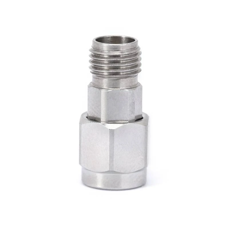

If you're interested in learning more about SMA Attenuators, you can check out our SMA Attenuators page on our website.
Understanding Attenuation
Attenuation is measured in decibels (dB). A positive dB value indicates a reduction in signal power. For example, a 3 dB attenuator will reduce the power of a signal by half. The formula for calculating the power ratio in decibels is:
[
\text{Attenuation (dB)} = 10 \log_{10} \left( \frac{P_{in}}{P_{out}} \right)
]
Where (P_{in}) is the input power and (P_{out}) is the output power.
Calculating Total Attenuation for Multiple Attenuators
When multiple SMA attenuators are connected in series, the total attenuation is simply the sum of the individual attenuations. Let's say you have three SMA attenuators with attenuations of 3 dB, 6 dB, and 10 dB respectively. To find the total attenuation, you just add these values together:
[
\text{Total Attenuation} = 3 \text{ dB} + 6 \text{ dB} + 10 \text{ dB} = 19 \text{ dB}
]
It's that simple! This is because when attenuators are connected in series, the output of one attenuator becomes the input of the next. Each attenuator reduces the signal power by its specified amount, and the overall reduction is the sum of these individual reductions.
Example Calculation
Let's work through a more detailed example. Suppose you have an input signal with a power of 100 mW. You connect two SMA attenuators in series: one with a 6 dB attenuation and another with a 10 dB attenuation.
First, let's calculate the output power after the first attenuator. Using the attenuation formula:
[
6 \text{ dB} = 10 \log_{10} \left( \frac{100 \text{ mW}}{P_{out1}} \right)
]
[
\frac{6}{10} = \log_{10} \left( \frac{100 \text{ mW}}{P_{out1}} \right)
]
[
10^{0.6} = \frac{100 \text{ mW}}{P_{out1}}
]
[
P_{out1} = \frac{100 \text{ mW}}{10^{0.6}} \approx 25.12 \text{ mW}
]
Now, this output power becomes the input power for the second attenuator. We'll calculate the output power after the second attenuator:
[
10 \text{ dB} = 10 \log_{10} \left( \frac{25.12 \text{ mW}}{P_{out2}} \right)
]
[
1 = \log_{10} \left( \frac{25.12 \text{ mW}}{P_{out2}} \right)
]
[
10^1 = \frac{25.12 \text{ mW}}{P_{out2}}
]
[
P_{out2} = \frac{25.12 \text{ mW}}{10} = 2.512 \text{ mW}
]
We can also calculate the total attenuation directly:
[
\text{Total Attenuation} = 6 \text{ dB} + 10 \text{ dB} = 16 \text{ dB}
]
Using the total attenuation to find the final output power:
[
16 \text{ dB} = 10 \log_{10} \left( \frac{100 \text{ mW}}{P_{final}} \right)
]
[
\frac{16}{10} = \log_{10} \left( \frac{100 \text{ mW}}{P_{final}} \right)
]
[
10^{1.6} = \frac{100 \text{ mW}}{P_{final}}
]
[
P_{final} = \frac{100 \text{ mW}}{10^{1.6}} \approx 2.512 \text{ mW}
]
As you can see, both methods give us the same result.
Other Considerations
While calculating the total attenuation is straightforward when attenuators are connected in series, there are a few other things to keep in mind:
- Impedance Matching: Make sure that all the attenuators have the same impedance. Mismatched impedance can cause signal reflections and affect the performance of your system.
- Frequency Response: Different attenuators may have different frequency responses. Make sure the attenuators you choose are suitable for the frequency range of your application.
Related Products
In addition to SMA Attenuators, we also offer 2.92mm Attenuators and 2.4mm Attenuators. These are also popular types of RF attenuators used in high-frequency applications.
Conclusion
Calculating the total attenuation when multiple SMA attenuators are connected is a simple process. Just add up the individual attenuations to get the total. Remember to consider impedance matching and frequency response when choosing your attenuators.
If you have any questions or need help selecting the right attenuators for your application, don't hesitate to reach out. We're here to assist you with all your RF component needs. Whether you're a hobbyist or a professional in the industry, we have the products and expertise to meet your requirements. Contact us today to start a conversation about your procurement needs.
References
- Pozar, D. M. (2011). Microwave Engineering (4th ed.). Wiley.
- Collin, R. E. (2001). Foundations for Microwave Engineering (2nd ed.). Wiley.


