

How to install phase trimmers?
Leave a message

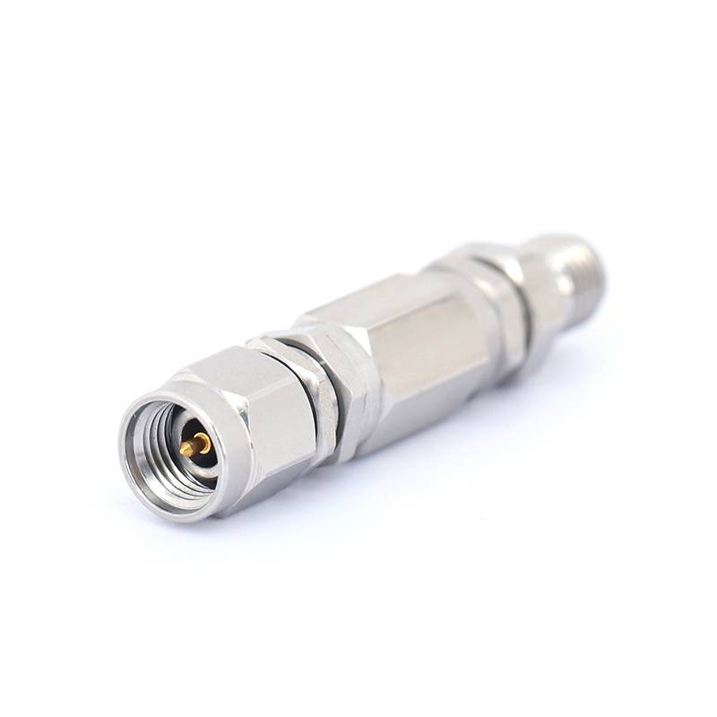
Hey there! As a supplier of Phase Trimmers, I'm super stoked to share with you how to install these nifty devices. Phase Trimmers, which you can check out Phase Trimmers, are essential components in many electronic systems, and getting them installed correctly is key to ensuring optimal performance.
Why Install Phase Trimmers?
Before we dive into the installation process, let's quickly talk about why you'd want to use Phase Trimmers in the first place. These little gadgets are used to adjust the phase of an electrical signal. In RF (Radio Frequency) systems, for example, precise phase control can improve signal quality, reduce interference, and enhance overall system efficiency. Whether you're working on a wireless communication system, a radar device, or a test and measurement setup, Phase Trimmers can make a big difference.
Tools You'll Need
Alright, let's get down to business. First things first, you'll need to gather the right tools for the job. Here's what I usually recommend:
- Soldering Iron: A good quality soldering iron is a must. Make sure it has adjustable temperature settings so you can set it to the right level for the type of solder and components you're using.
- Solder: Choose a high-quality solder that's appropriate for electronic work. Lead-free solder is a popular choice these days due to environmental concerns.
- Desoldering Pump or Wick: Mistakes happen, and if you need to remove a soldered connection, a desoldering pump or wick will come in handy.
- Screwdriver Set: Depending on the enclosure or mounting method of your Phase Trimmer, you might need a set of screwdrivers to open cases or secure the device in place.
- Multimeter: This tool is essential for testing the electrical characteristics of your Phase Trimmer before and after installation. It can help you verify that the device is working correctly and that the phase adjustments are within the desired range.
- Anti-Static Wrist Strap: Electronic components are sensitive to static electricity, so wearing an anti-static wrist strap can prevent damage to your Phase Trimmer during handling.
Pre-Installation Checks
Before you start soldering or mounting anything, it's important to do a few pre-installation checks. First, take a close look at your Phase Trimmer. Make sure there are no visible signs of damage, such as bent pins, cracked housing, or loose components. If you notice any issues, contact your supplier (like us!) to get a replacement.
Next, refer to the datasheet for your Phase Trimmer. The datasheet will provide important information about the device's electrical specifications, pinout, and recommended operating conditions. Pay special attention to the pinout diagram, as this will show you which pins are used for power, ground, input, output, and phase adjustment.
Mounting the Phase Trimmer
Once you've completed the pre-installation checks, it's time to mount the Phase Trimmer. The mounting method will depend on the type of Phase Trimmer you have and the requirements of your system. Here are a few common mounting options:
- PCB Mounting: Many Phase Trimmers are designed to be mounted directly on a printed circuit board (PCB). If you're using this method, align the pins of the Phase Trimmer with the corresponding holes on the PCB. Make sure the device is sitting flat and that the pins are fully inserted into the holes.
- Panel Mounting: Some Phase Trimmers are designed to be mounted on a panel, such as the front or back of an enclosure. If you're using this method, use a screwdriver to secure the Phase Trimmer to the panel using the appropriate mounting holes or brackets.
- Chassis Mounting: In some cases, you might need to mount the Phase Trimmer directly to the chassis of your system. This can provide better heat dissipation and mechanical stability. Use a suitable mounting bracket or hardware to secure the device to the chassis.
Soldering the Phase Trimmer
If you're mounting the Phase Trimmer on a PCB, soldering is the next step. Here's how to do it:
- Prepare the Soldering Iron: Set the temperature of your soldering iron to the recommended level for the type of solder you're using. Allow the soldering iron to heat up for a few minutes before you start soldering.
- Apply Solder to the Pins: Dip the tip of the soldering iron into the solder to coat it with a small amount of solder. This will help transfer heat more efficiently. Then, touch the tip of the soldering iron to the pin and the PCB pad simultaneously. Hold the soldering iron in place for a few seconds to heat up the pin and the pad.
- Add Solder: Once the pin and the pad are heated, touch the solder wire to the joint. The solder should melt and flow around the pin and the pad, creating a solid connection. Be careful not to use too much solder, as this can cause shorts or other issues.
- Remove the Soldering Iron: After the solder has flowed around the pin and the pad, remove the soldering iron from the joint. Hold the Phase Trimmer in place for a few seconds to allow the solder to cool and solidify.
- Inspect the Joints: Once all the pins are soldered, inspect the joints carefully. Make sure there are no cold solder joints (which look dull and grainy), shorts (where the solder has bridged between two adjacent pins), or other issues. If you notice any problems, use a desoldering pump or wick to remove the solder and re-solder the joint.
Testing the Phase Trimmer
After the Phase Trimmer is installed and soldered, it's time to test it. Here's how to do it:
- Power On the System: Make sure your system is powered on and that all the necessary components are functioning correctly.
- Connect the Multimeter: Use a multimeter to measure the voltage, current, and resistance of the Phase Trimmer. Refer to the datasheet for the recommended values and compare them to your measurements.
- Adjust the Phase: Use the phase adjustment mechanism on the Phase Trimmer to make small adjustments to the phase of the signal. Monitor the output of the Phase Trimmer using a spectrum analyzer or other suitable test equipment to verify that the phase adjustments are working correctly.
- Check for Stability: Leave the system running for a few minutes and monitor the output of the Phase Trimmer. Make sure the phase adjustments are stable and that there are no fluctuations or drift over time.
Troubleshooting
If you encounter any problems during the installation or testing process, don't panic. Here are a few common issues and how to troubleshoot them:
- No Output Signal: If the Phase Trimmer is not producing an output signal, check the power supply, the input signal, and the soldered connections. Make sure the power supply is providing the correct voltage and that the input signal is within the specified range. If the soldered connections are loose or damaged, re-solder them.
- Incorrect Phase Adjustment: If the phase adjustments are not working correctly, check the phase adjustment mechanism on the Phase Trimmer. Make sure it is not damaged or stuck. If necessary, refer to the datasheet for instructions on how to adjust the phase correctly.
- Overheating: If the Phase Trimmer is overheating, check the power dissipation and the heat dissipation mechanism. Make sure the device is not being operated beyond its recommended power rating and that there is adequate ventilation or heat sinking.
Conclusion
Installing Phase Trimmers might seem like a daunting task, but with the right tools, knowledge, and a little patience, you can do it like a pro. Remember to follow the pre-installation checks, choose the right mounting method, solder the pins carefully, and test the device thoroughly. If you have any questions or need further assistance, don't hesitate to reach out to us. As a supplier of Phase Trimmers, we're here to help you get the most out of your devices.
If you're interested in purchasing Phase Trimmers or have any other questions about our products, feel free to contact us for a consultation. We'll be happy to discuss your specific needs and provide you with the best solutions for your application.

References
- Manufacturer's datasheets for Phase Trimmers
- Electronic engineering textbooks on RF and microwave circuits


