How to match the input impedance of an RF amplifier?
Leave a message
Hey there! As a supplier of RF amplifiers, I've seen firsthand how crucial it is to match the input impedance of an RF amplifier. It's like the secret sauce that can make or break the performance of your RF system. In this blog, I'm going to share some tips and tricks on how to do it right.
Why is Input Impedance Matching Important?
Before we dive into the how-to, let's quickly talk about why input impedance matching is so important. When the input impedance of an RF amplifier is not matched to the source impedance, it can lead to a whole bunch of problems. For starters, you'll get reflections. These reflections can cause signal loss, distortion, and even damage to your equipment.
Imagine you're trying to send a signal down a cable. If the cable's impedance doesn't match the source or the load, the signal will bounce back and forth, creating interference. This is like trying to push a ball through a narrow tube that's too small for it - it just doesn't work smoothly.
Matching the input impedance ensures that the maximum amount of power is transferred from the source to the amplifier. This means better signal quality, less noise, and overall improved performance. It's like making sure your car's engine is properly tuned - everything runs more efficiently.
Understanding Impedance Basics
Let's start with the basics. Impedance is a measure of how much a circuit resists the flow of alternating current (AC). It's a combination of resistance (R), inductance (L), and capacitance (C), and is represented by the symbol Z. In an RF system, impedance is usually measured in ohms (Ω).
The most common impedance value in RF systems is 50 Ω. This is because it provides a good balance between power handling and signal loss. However, different applications may require different impedance values. For example, some systems may use 75 Ω for better performance in video or cable TV applications.
When we talk about impedance matching, we're trying to make the input impedance of the amplifier (Zin) equal to the source impedance (Zs). This is known as a conjugate match, where the real parts of the impedances are equal, and the imaginary parts are equal in magnitude but opposite in sign.
Methods for Matching Input Impedance
1. Using Passive Components
One of the most common ways to match the input impedance of an RF amplifier is by using passive components like resistors, capacitors, and inductors. These components can be arranged in different configurations to create a matching network.
- L - Networks: An L - network is a simple and effective way to match impedance. It consists of two reactive components (either an inductor and a capacitor or two inductors/capacitors) arranged in an L - shape. The values of the components are calculated based on the source and load impedances and the operating frequency.
- Pi - Networks and T - Networks: These are more complex networks that offer more flexibility in impedance matching. Pi - networks have a configuration that looks like the Greek letter π, while T - networks look like the letter T. They can be used to match a wider range of impedances and are often used in more complex RF systems.
For example, if you have a source impedance of 50 Ω and an amplifier input impedance of 200 Ω, you can design an L - network using an inductor and a capacitor to transform the 200 Ω impedance to 50 Ω at the desired frequency.

2. Transmission Line Matching
Another method is to use transmission lines. Transmission lines, such as coaxial cables or microstrip lines, can be used to match impedance by adjusting their length and characteristic impedance.
- Quarter - Wave Transformer: A quarter - wave transformer is a section of transmission line that is one - quarter wavelength long at the operating frequency. By choosing the appropriate characteristic impedance of the transmission line, you can match the source impedance to the load impedance. For example, if you have a source impedance of 50 Ω and a load impedance of 200 Ω, you can use a quarter - wave transformer with a characteristic impedance of √(50 × 200)=100 Ω.
3. Using Matching Networks in Amplifier Design
Many RF amplifiers come with built - in matching networks. These networks are designed during the amplifier's development to ensure that the input impedance is matched to the typical source impedance in the application. However, in some cases, you may need to adjust or modify these networks to optimize the performance for your specific system.
Measuring and Verifying Impedance Matching
Once you've designed and implemented your impedance matching network, it's important to measure and verify that the input impedance is indeed matched. You can use a network analyzer to measure the scattering parameters (S - parameters) of the amplifier. The S11 parameter, in particular, gives you information about the reflection coefficient at the input of the amplifier. A low S11 value (close to - 20 dB or lower) indicates good impedance matching.
You can also use a vector network analyzer (VNA) to get more detailed information about the impedance, including the real and imaginary parts. This can help you fine - tune your matching network if necessary.
Practical Tips for Input Impedance Matching
- Consider the Frequency Range: Impedance matching is frequency - dependent. Make sure your matching network is designed to work over the entire frequency range of your RF system. If you're working with a wideband system, you may need to use more complex matching networks or techniques.
- Account for Component Tolerances: Real - world components have tolerances, which means their actual values may deviate from the nominal values. When designing your matching network, take these tolerances into account to ensure that the impedance matching is still effective.
- Keep it Simple: In many cases, a simple matching network can be just as effective as a complex one. Don't overcomplicate things unless necessary. A simple L - network may be sufficient for many applications.
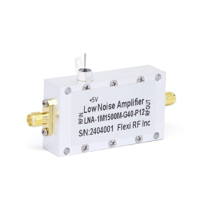
Low Noise Amplifiers
If you're looking for high - performance RF amplifiers, you might be interested in our Low Noise Amplifiers. These amplifiers are designed to provide low noise figure and high gain, making them ideal for applications where signal quality is critical.
Conclusion
Matching the input impedance of an RF amplifier is an essential step in ensuring the optimal performance of your RF system. By understanding the basics of impedance, using the right matching methods, and verifying the results, you can minimize reflections, improve signal quality, and increase power transfer efficiency.
If you're interested in purchasing RF amplifiers or need more information on impedance matching, feel free to reach out to us. We're here to help you find the best solution for your specific needs.
References
- Pozar, D. M. (2011). Microwave Engineering. Wiley.
- Collin, R. E. (2001). Foundations for Microwave Engineering. Wiley.


