How to measure the power division ratio of power dividers?
Leave a message
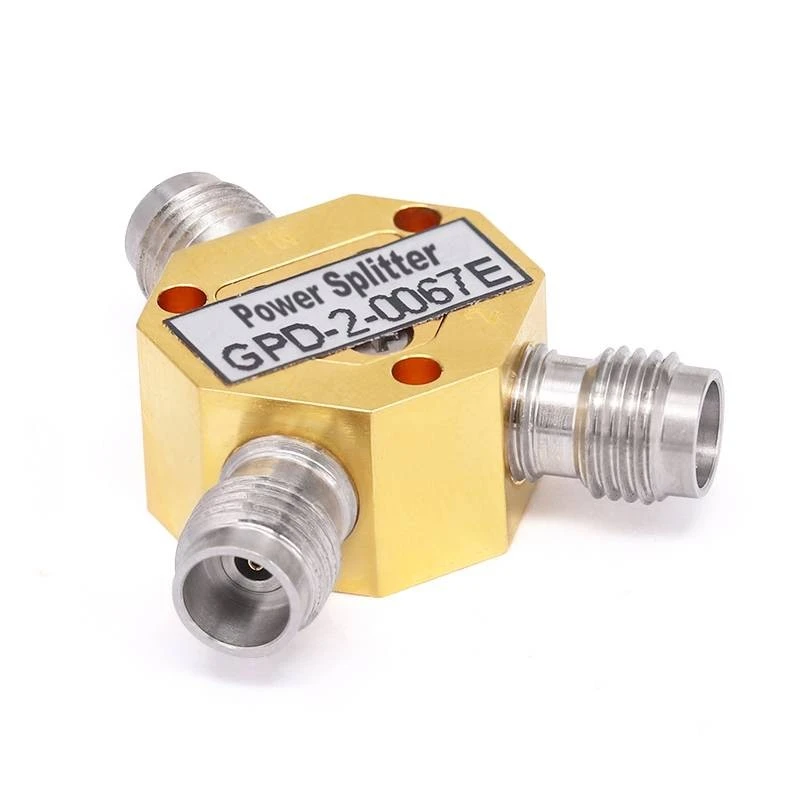
Power dividers are crucial components in various RF and microwave systems, used to split an input signal into multiple output signals. One of the key parameters of a power divider is its power division ratio, which indicates how the input power is distributed among the output ports. As a power dividers supplier, we understand the importance of accurately measuring this ratio. In this blog, we will explore different methods to measure the power division ratio of power dividers.
Understanding Power Division Ratio
Before delving into the measurement methods, it's essential to understand what the power division ratio represents. The power division ratio is defined as the ratio of the power at each output port to the total output power or the input power. For example, in an ideal 2 - way power divider with equal power division, the power division ratio for each output port is 1:1, meaning that each output port receives half of the input power.
Measurement Equipment
To measure the power division ratio of power dividers, we need specific equipment. Here are the commonly used tools:
- Power Meter: A power meter is used to measure the power of an RF or microwave signal. It provides accurate power readings and is available in different frequency ranges and power levels.
- Signal Generator: A signal generator is used to generate a stable RF or microwave signal with a known frequency and power level. It serves as the input source for the power divider under test.
- Spectrum Analyzer: A spectrum analyzer can be used to analyze the frequency spectrum of the input and output signals. It helps in identifying any unwanted signals or interference that may affect the measurement accuracy.
Measurement Methods
Method 1: Direct Power Measurement
The direct power measurement method is the most straightforward way to measure the power division ratio. Here are the steps:
- Set up the equipment: Connect the signal generator to the input port of the power divider. Then, connect a power meter to each output port of the power divider.
- Generate the input signal: Set the signal generator to generate a continuous - wave (CW) signal with a specific frequency and power level. For example, you can set the frequency to 2 GHz and the power level to 0 dBm.
- Measure the output power: Read the power values displayed on each power meter. Let (P_1, P_2,\cdots, P_n) be the power values measured at the (n) output ports of the power divider.
- Calculate the power division ratio: The power division ratio for each output port (i) can be calculated as (r_i=\frac{P_i}{\sum_{j = 1}^{n}P_j}).
For instance, if we have a 2 - Way Power Dividers and measure (P_1 = 0.5) mW and (P_2 = 0.5) mW at the two output ports, the total output power (P_{total}=P_1 + P_2=1) mW. The power division ratio for each port is (r_1=\frac{0.5}{1}=0.5) and (r_2=\frac{0.5}{1}=0.5), indicating an equal power division.
Method 2: Using a Spectrum Analyzer
A spectrum analyzer can also be used to measure the power division ratio, especially when dealing with complex signals or when we need to analyze the frequency - domain characteristics. Here are the steps:
- Set up the equipment: Connect the signal generator to the input port of the power divider. Connect the output ports of the power divider to the spectrum analyzer using appropriate cables.
- Generate the input signal: Set the signal generator to generate a signal with a specific frequency and power level. You can choose a modulated signal, such as a frequency - modulated (FM) or amplitude - modulated (AM) signal, if needed.
- Analyze the output signals: Use the spectrum analyzer to display the frequency spectrum of the output signals. Measure the peak power of each output signal at the desired frequency.
- Calculate the power division ratio: Similar to the direct power measurement method, calculate the power division ratio using the measured peak power values.
This method is useful when we want to check the frequency response of the power divider and ensure that the power division ratio is consistent across different frequencies.
Method 3: Network Analyzer Measurement
A network analyzer is a powerful tool for measuring the scattering parameters (S - parameters) of a power divider. The S - parameters can be used to calculate the power division ratio. Here are the steps:
- Calibrate the network analyzer: Before making any measurements, calibrate the network analyzer using a calibration kit. This ensures accurate measurement results.
- Connect the power divider: Connect the power divider to the network analyzer. The network analyzer will measure the S - parameters of the power divider, including (S_{21}, S_{31},\cdots, S_{n1}), which represent the transmission coefficients from the input port to the output ports.
- Calculate the power division ratio: The power division ratio for each output port (i) can be calculated as (r_i=\frac{|S_{i1}|^2}{\sum_{j = 2}^{n}|S_{j1}|^2}).
The advantage of using a network analyzer is that it can provide comprehensive information about the power divider, such as insertion loss, return loss, and phase balance, in addition to the power division ratio.
Factors Affecting Measurement Accuracy
Several factors can affect the accuracy of power division ratio measurements. Here are some of the main factors:
- Measurement Equipment Accuracy: The accuracy of the power meter, signal generator, and spectrum analyzer or network analyzer used in the measurement process directly affects the measurement accuracy. Make sure to use high - quality equipment and calibrate them regularly.
- Cable Loss: The cables used to connect the equipment can introduce loss, especially at high frequencies. Use low - loss cables and compensate for the cable loss in the measurement results.
- Environmental Conditions: Environmental factors such as temperature, humidity, and electromagnetic interference can affect the performance of the power divider and the measurement equipment. Conduct the measurements in a controlled environment and shield the equipment from external interference.
Importance of Accurate Measurement
Accurately measuring the power division ratio of power dividers is crucial for several reasons:
- System Performance: In RF and microwave systems, the power division ratio affects the overall system performance. If the power division ratio is not accurate, it can lead to imbalances in the system, resulting in reduced signal quality and increased interference.
- Compliance with Standards: Many applications have specific requirements for the power division ratio. Measuring the power division ratio accurately ensures that the power dividers meet the relevant standards and specifications.
- Product Quality Control: As a power dividers supplier, we need to ensure the quality of our products. Accurate measurement of the power division ratio is an essential part of our quality control process.
Conclusion
Measuring the power division ratio of power dividers is an important task that requires the use of appropriate equipment and measurement methods. We have discussed three main methods: direct power measurement, using a spectrum analyzer, and using a network analyzer. Each method has its own advantages and is suitable for different situations.

At our company, we offer a wide range of power dividers, including 2 - Way Power Dividers, 4 - Way Power Dividers, and 16 - Way Power Dividers. We ensure the high quality of our products through strict quality control measures, including accurate measurement of the power division ratio.
If you are interested in purchasing power dividers or have any questions about power division ratio measurement, please feel free to contact us. We are ready to provide you with professional advice and high - quality products.
References
- Pozar, D. M. (2011). Microwave Engineering. Wiley.
- Collin, R. E. (2001). Foundations for Microwave Engineering. Wiley.


