How to design a power divider?
Leave a message
Designing a power divider is a crucial task in the field of RF and microwave engineering. As a power dividers supplier, I have gained extensive experience in this area. In this blog post, I will share some key aspects of power divider design, including the basic principles, different types, and important design considerations.
Basic Principles of Power Dividers
A power divider is a passive device that splits an input signal into two or more output signals. The fundamental principle behind a power divider is to distribute the power of the input signal evenly among the output ports while maintaining certain electrical characteristics such as impedance matching and isolation between ports.
The most common type of power divider is the Wilkinson power divider, which was first proposed by Ernest J. Wilkinson in 1960. The Wilkinson power divider uses quarter - wave transformers and a resistor to achieve power division and isolation between the output ports. The quarter - wave transformers are used to match the impedance of the input and output ports, and the resistor is used to provide isolation between the output ports.
Another important principle is the conservation of power. According to the law of conservation of energy, the sum of the powers at the output ports of a power divider should be equal to the power at the input port, neglecting any losses in the device. Mathematically, if (P_{in}) is the input power and (P_{out1},P_{out2},\cdots,P_{outn}) are the output powers of an (n) - way power divider, then (P_{in}=\sum_{i = 1}^{n}P_{outi}).
Different Types of Power Dividers
Two - Way Power Dividers
Two - way power dividers are the simplest form of power dividers. They split the input signal into two equal - power output signals. The Wilkinson two - way power divider is widely used due to its good isolation between the output ports and relatively low insertion loss.
Multi - Way Power Dividers
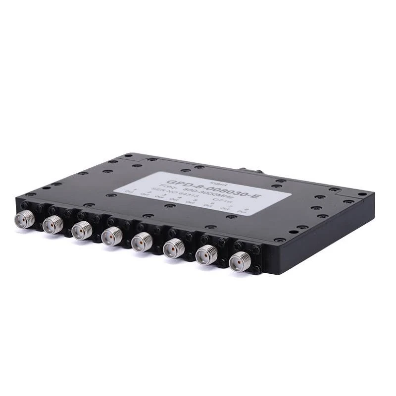
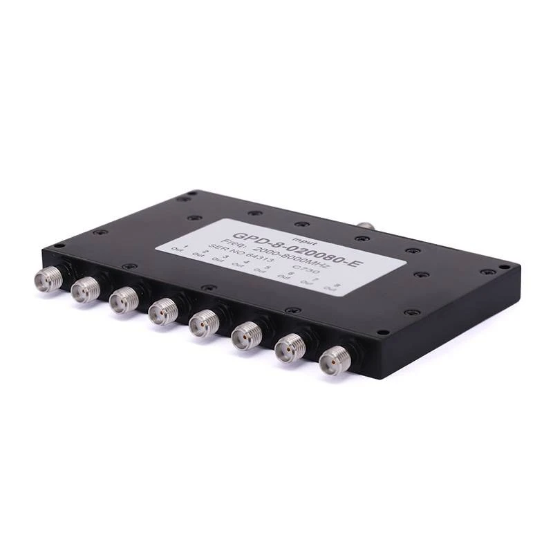
For applications that require more than two output signals, multi - way power dividers are used. For example, 3 - Way Power Dividers can split the input signal into three output signals, 6 - Way Power Dividers into six, and 8 - Way Power Dividers into eight. These multi - way power dividers can be designed by cascading two - way power dividers or using more complex circuit topologies.
Unequal Power Dividers
In some cases, it is necessary to divide the power unequally among the output ports. Unequal power dividers can be designed by adjusting the impedance values of the transmission lines and the resistor values in the circuit. For example, a power divider with a power division ratio of 2:1 can be designed to provide more power to one output port than the other.
Design Considerations
Impedance Matching
Impedance matching is one of the most important design considerations for power dividers. The input and output ports of a power divider should be matched to the characteristic impedance of the system, typically 50 ohms in RF and microwave applications. Mismatched impedance can lead to reflections, which increase insertion loss and reduce the efficiency of the power divider.
To achieve impedance matching, quarter - wave transformers are commonly used. The characteristic impedance of the quarter - wave transformer is calculated based on the input and output impedances of the power divider. For a Wilkinson power divider, the characteristic impedance of the quarter - wave transformer (Z_{01}) is given by (Z_{01}=\sqrt{2}Z_{0}), where (Z_{0}) is the system impedance.
Isolation
Isolation between the output ports is another critical factor. Good isolation ensures that the signals at the output ports do not interfere with each other. In a Wilkinson power divider, the resistor between the output ports provides isolation. The value of the resistor is chosen to optimize the isolation performance. For a two - way Wilkinson power divider with a system impedance (Z_{0}), the resistor value (R = 2Z_{0}).
Bandwidth
The bandwidth of a power divider refers to the range of frequencies over which the power divider can operate effectively. The bandwidth is affected by factors such as the type of transmission lines used, the impedance matching network, and the isolation circuit. Generally, power dividers with wider bandwidths are more difficult to design and may have higher insertion losses.
Insertion Loss
Insertion loss is the loss of power that occurs when the signal passes through the power divider. It is mainly caused by factors such as conductor losses, dielectric losses, and radiation losses. Low insertion loss is desirable in power divider design to ensure efficient power transfer.
Design Steps
Step 1: Define the Specifications
The first step in designing a power divider is to define the specifications, including the number of output ports, the power division ratio, the operating frequency range, the system impedance, and the required isolation and insertion loss.
Step 2: Choose the Topology
Based on the specifications, choose an appropriate power divider topology. For example, if good isolation and low insertion loss are required, a Wilkinson power divider may be a good choice.
Step 3: Calculate the Component Values
Once the topology is chosen, calculate the values of the components such as the characteristic impedance of the transmission lines and the resistor values. Use the relevant formulas and design equations for the chosen topology.
Step 4: Simulate the Design
Use electromagnetic simulation software such as ADS (Advanced Design System) or HFSS (High - Frequency Structure Simulator) to simulate the design. The simulation results can help verify the performance of the power divider and identify any potential problems.
Step 5: Fabricate and Test
After the simulation results are satisfactory, fabricate the power divider using appropriate manufacturing processes such as printed circuit board (PCB) fabrication or microfabrication. Then, test the fabricated power divider using network analyzers and other test equipment to ensure that it meets the specifications.
Conclusion
Designing a power divider requires a good understanding of the basic principles, different types, and important design considerations. As a power dividers supplier, we are committed to providing high - quality power dividers that meet the diverse needs of our customers. Whether you need a simple two - way power divider or a complex multi - way power divider, we have the expertise and technology to design and manufacture the right product for you.
If you are interested in our power dividers or have any questions about power divider design, please feel free to contact us for procurement and further discussions.
References
- Pozar, D. M. (2011). Microwave Engineering (4th ed.). Wiley.
- Wilkinson, E. J. (1960). An N - way hybrid power divider. IRE Transactions on Microwave Theory and Techniques, 8(1), 116 - 118.


