How to ensure the stability of an RF amplifier?
Leave a message
Yo, fellow RF enthusiasts! As a supplier of RF amplifiers, I've seen firsthand how crucial it is to keep these bad boys stable. In this blog, I'm gonna share some tips on how to ensure the stability of an RF amplifier.
Let's start with the basics. What exactly is stability in an RF amplifier? Well, in simple terms, a stable amplifier is one that doesn't oscillate or go haywire under normal operating conditions. Oscillations can mess up the signal, cause interference, and even damage the amplifier itself. So, we definitely want to avoid that.
1. Proper Component Selection
The first step in ensuring amplifier stability is choosing the right components. This includes transistors, resistors, capacitors, and inductors. Each component plays a vital role in the amplifier's performance, and using low - quality or mismatched parts can lead to instability.
For transistors, we need to look at parameters like gain, noise figure, and power handling. A transistor with too high a gain can make the amplifier prone to oscillations. On the other hand, a transistor with a low gain might not provide enough amplification. We also need to consider the frequency range of the transistor. It should be suitable for the operating frequency of our amplifier.
Resistors, capacitors, and inductors are used for biasing, coupling, and matching. For example, the biasing resistors set the DC operating point of the transistor. If these resistors are not properly selected, the transistor might not operate in the desired region, leading to instability. Capacitors and inductors are used for impedance matching. A good impedance match between the amplifier and the load helps to transfer power efficiently and reduces the chances of reflections, which can cause oscillations.
2. Input and Output Matching
Impedance matching is super important for amplifier stability. When the input and output impedances of the amplifier are matched to the source and load impedances respectively, we can minimize reflections. Reflections can cause standing waves in the amplifier, which can lead to oscillations.
We can use various techniques for impedance matching, such as using matching networks. These networks can be made up of capacitors and inductors. For example, a simple L - network can be used to match a load impedance to the amplifier's output impedance. There are also more complex matching networks like the Pi - network and T - network, which can provide better matching over a wider frequency range.
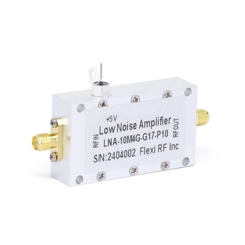
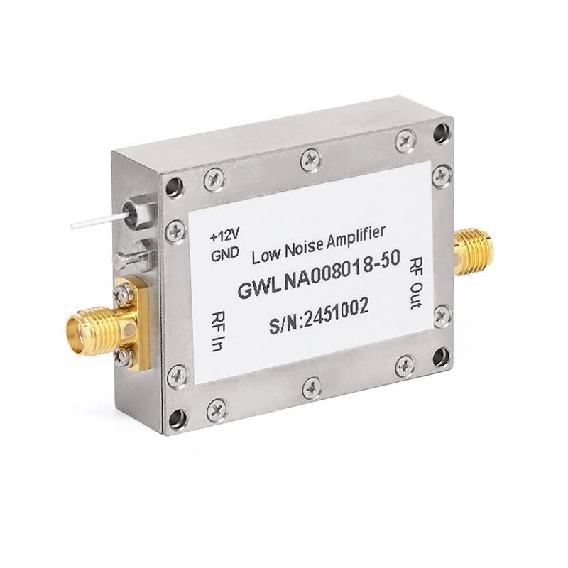
At our company, we offer a range of RF amplifiers with excellent input and output matching. Check out our 220GHz Low Noise Amplifiers, 90GHz Low Noise Amplifiers, and 18GHz Low Noise Amplifiers. These amplifiers are designed with proper matching networks to ensure stable operation.
3. Biasing Circuits
Biasing is another key factor in amplifier stability. The biasing circuit sets the DC operating point of the transistor. A stable biasing circuit ensures that the transistor operates in the linear region, where it can provide consistent amplification.
There are different types of biasing circuits, such as fixed - bias, self - bias, and voltage - divider bias. Voltage - divider bias is one of the most commonly used biasing circuits because it provides good stability over a wide range of operating conditions. It uses two resistors to divide the supply voltage and set the base voltage of the transistor.
When designing the biasing circuit, we need to consider factors like temperature changes. Transistors are sensitive to temperature, and their characteristics can change with temperature. A good biasing circuit should be able to compensate for these temperature changes and keep the operating point stable.
4. PCB Layout
The printed circuit board (PCB) layout can have a big impact on amplifier stability. A poorly designed PCB layout can introduce unwanted parasitic capacitances and inductances, which can cause oscillations.
We need to pay attention to the following points when designing the PCB layout:
- Component Placement: Place the components close together to minimize the length of the interconnecting traces. Long traces can act as antennas and radiate electromagnetic energy, which can cause interference and instability.
- Grounding: A proper grounding scheme is essential. We should use a single - point ground or a star - ground configuration to avoid ground loops. Ground loops can introduce noise and cause instability in the amplifier.
- Power Supply Decoupling: Use decoupling capacitors near the power supply pins of the components. These capacitors help to filter out high - frequency noise from the power supply and prevent it from affecting the amplifier's performance.
5. Feedback
Feedback can be used to improve amplifier stability. There are two types of feedback: positive feedback and negative feedback. Positive feedback can increase the gain of the amplifier, but it can also make the amplifier unstable. Negative feedback, on the other hand, can reduce the gain but improve the stability, linearity, and bandwidth of the amplifier.
We can use negative feedback to control the gain of the amplifier and reduce the effects of parameter variations. For example, we can use a resistor in the feedback path to set the gain of the amplifier. By adjusting the value of this resistor, we can control the amount of negative feedback and thus the gain of the amplifier.
6. Thermal Management
Heat can have a significant impact on amplifier stability. As the temperature of the amplifier increases, the characteristics of the components can change, which can lead to instability.
We need to ensure proper thermal management of the amplifier. This can be done by using heat sinks, fans, or other cooling devices. Heat sinks are used to dissipate the heat generated by the components. They increase the surface area of the component, allowing it to transfer heat more efficiently to the surrounding environment. Fans can be used to increase the airflow over the heat sink, further improving the cooling efficiency.
7. Testing and Monitoring
Once the amplifier is designed and built, we need to test and monitor its performance. We can use various test equipment, such as spectrum analyzers, network analyzers, and oscilloscopes, to measure the amplifier's gain, frequency response, and stability.
During the testing process, we can look for signs of instability, such as oscillations or abnormal frequency responses. If we detect any problems, we can make adjustments to the amplifier's design or components to improve its stability.
We also need to monitor the amplifier's performance over time. Environmental factors like temperature and humidity can change, and these changes can affect the amplifier's stability. By monitoring the amplifier's performance, we can detect any changes early and take corrective actions.
In conclusion, ensuring the stability of an RF amplifier requires a combination of proper component selection, impedance matching, biasing, PCB layout, feedback, thermal management, and testing. At our company, we take all these factors into account when designing and manufacturing our RF amplifiers. We are committed to providing high - quality, stable RF amplifiers to our customers.
If you're interested in purchasing RF amplifiers or have any questions about amplifier stability, don't hesitate to reach out to us. We're here to help you find the best solution for your needs.
References
- Gonzalez, Guillermo. Microwave Transistor Amplifiers: Analysis and Design. Prentice Hall, 1997.
- Pozar, David M. Microwave Engineering. Wiley, 2011.


