How to integrate RF circulators into a printed circuit board?
Leave a message
Integrating RF circulators into a printed circuit board (PCB) is a crucial step in many RF and microwave applications. As a supplier of RF circulators, I've witnessed firsthand the importance of proper integration to ensure optimal performance and reliability. In this blog post, I'll share some insights and best practices on how to integrate RF circulators into a PCB effectively.
Understanding RF Circulators
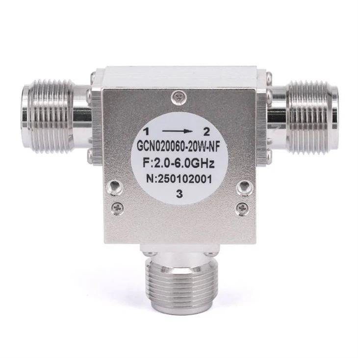
Before diving into the integration process, it's essential to have a basic understanding of RF circulators. An RF circulator is a passive, non - reciprocal three - or four - port device that allows the flow of RF signals in a specific direction. In a three - port circulator, for example, a signal entering port 1 exits from port 2, a signal entering port 2 exits from port 3, and a signal entering port 3 exits from port 1.
RF circulators are commonly used in RF systems for various purposes, such as isolating transmitters from receivers, protecting sensitive components from reflected power, and enabling duplex operation. They are available in different types, including coaxial and planar designs. The RF Coaxial Circulators are particularly popular due to their high power handling capabilities and wide frequency range.
Design Considerations
1. Frequency Range
The first step in integrating an RF circulator into a PCB is to consider the operating frequency range of the system. Different RF circulators are designed to operate within specific frequency bands. It's crucial to select a circulator that matches the frequency requirements of your application. The datasheet of the circulator will provide detailed information about its frequency response, insertion loss, and isolation.
2. Power Handling
Another important consideration is the power handling capacity of the circulator. The power level of the RF signals in your system will determine the appropriate circulator to use. If the power exceeds the rated capacity of the circulator, it can lead to overheating, reduced performance, and even damage to the device. Make sure to choose a circulator with a power handling capability that is sufficient for your application.
3. PCB Layout
The layout of the PCB plays a significant role in the performance of the integrated RF circulator. Here are some key layout considerations:
- Grounding: Proper grounding is essential for minimizing electromagnetic interference (EMI) and ensuring stable performance. The circulator should be grounded to a solid ground plane on the PCB. Use wide ground traces and vias to provide a low - impedance path for the ground current.
- Trace Length and Width: The length and width of the RF traces connecting the circulator to other components on the PCB can affect the signal integrity. Keep the trace lengths as short as possible to minimize insertion loss and phase shift. The width of the traces should be designed to match the characteristic impedance of the system, typically 50 ohms.
- Isolation: To prevent coupling between different ports of the circulator and other components on the PCB, provide sufficient isolation. This can be achieved by using ground planes, shielding, and proper spacing between traces.
Integration Steps
1. Component Placement
Once you have selected the appropriate RF circulator and designed the PCB layout, the next step is to place the circulator on the PCB. Here are some guidelines for component placement:
- Accessibility: Place the circulator in a location that is easily accessible for testing and maintenance. This will make it easier to troubleshoot any issues that may arise during the development or operation of the system.
- Thermal Considerations: If the circulator generates a significant amount of heat, place it in an area with good ventilation or near a heat sink. This will help to dissipate the heat and prevent overheating.
- Proximity to Other Components: Keep the circulator away from sensitive components that may be affected by its magnetic field. Also, ensure that there is enough space between the circulator and other components to avoid mechanical interference.
2. Soldering
Soldering is a critical step in the integration process. Here are some tips for soldering the RF circulator to the PCB:
- Use the Right Solder: Select a solder that is suitable for RF applications. Lead - free solders are commonly used due to environmental regulations. Make sure the solder has good wetting properties and a low melting point.
- Soldering Temperature and Time: Control the soldering temperature and time carefully to avoid damaging the circulator. Follow the manufacturer's recommendations for the soldering process. Excessive heat can cause the magnetic material in the circulator to degrade, leading to reduced performance.
- Solder Joint Quality: Ensure that the solder joints are clean, smooth, and free of defects. Use a soldering iron with a fine tip to make precise solder joints. Inspect the solder joints visually and use a microscope if necessary to detect any potential issues.
3. Testing and Validation
After soldering the circulator to the PCB, it's important to test and validate the performance of the integrated system. Here are some tests that can be performed:
- Insertion Loss and Isolation: Measure the insertion loss and isolation of the circulator using a network analyzer. Compare the measured values with the specifications provided in the datasheet. Any significant deviation from the specifications may indicate a problem with the integration process.
- Return Loss: Measure the return loss of the circulator to ensure that the impedance matching is correct. A high return loss indicates poor impedance matching, which can lead to signal reflections and reduced performance.
- Power Handling: Test the power handling capacity of the circulator by applying a high - power signal and monitoring the performance. Make sure the circulator can handle the rated power without overheating or experiencing any performance degradation.
Troubleshooting
If you encounter any issues during the integration process or testing, here are some common problems and solutions:
- High Insertion Loss: High insertion loss can be caused by improper soldering, incorrect trace lengths, or poor impedance matching. Check the solder joints, adjust the trace lengths, and ensure that the impedance of the traces is matched to the circulator.
- Low Isolation: Low isolation may be due to electromagnetic coupling between the ports of the circulator or other components on the PCB. Improve the isolation by using shielding, increasing the spacing between traces, or adding ferrite beads.
- Overheating: Overheating can be caused by excessive power dissipation or poor thermal management. Check the power handling capacity of the circulator and ensure that it is operating within its rated limits. Improve the thermal management by adding a heat sink or improving the ventilation.
Conclusion
Integrating RF circulators into a PCB requires careful consideration of various factors, including frequency range, power handling, PCB layout, and soldering. By following the best practices outlined in this blog post, you can ensure a successful integration and achieve optimal performance of your RF system.
As a supplier of RF circulators, we are committed to providing high - quality products and technical support to our customers. If you are interested in purchasing RF circulators or have any questions about integrating them into your PCB, please feel free to contact us for further discussion and procurement. We look forward to working with you to meet your RF application needs.

References
- Pozar, D. M. (2011). Microwave Engineering (4th ed.). Wiley.
- Collin, R. E. (2001). Foundations for Microwave Engineering (2nd ed.). Wiley.


