What is the efficiency of power dividers?
Leave a message
What is the efficiency of power dividers?
Power dividers are essential components in many RF and microwave systems, playing a crucial role in distributing power from a single input port to multiple output ports. As a supplier of power dividers, understanding the efficiency of these devices is of utmost importance, not only for us to provide high - quality products but also for our customers to make informed decisions when choosing the right power dividers for their applications.
Understanding Power Divider Efficiency
Efficiency in power dividers is a measure of how effectively the input power is distributed to the output ports with minimal losses. Mathematically, the efficiency (η) of a power divider is defined as the ratio of the total power delivered to the output ports (Pout_total) to the input power (Pin), expressed as a percentage:
η = (Pout_total / Pin) × 100%
In an ideal power divider, all the input power would be evenly distributed among the output ports, and the efficiency would be 100%. However, in real - world scenarios, various factors contribute to power losses, reducing the overall efficiency of the device.
Factors Affecting Power Divider Efficiency
1. Insertion Loss
Insertion loss is one of the primary factors that affect the efficiency of power dividers. It represents the power loss that occurs when the signal passes through the power divider. Insertion loss can be caused by several factors, including the resistance of the transmission lines, dielectric losses in the substrate material, and losses due to the coupling mechanisms within the power divider.
For example, in a microstrip - based power divider, the resistance of the microstrip lines can cause power dissipation in the form of heat. The higher the resistance, the greater the insertion loss and the lower the efficiency. Dielectric losses also play a significant role, especially at high frequencies. As the frequency increases, the dielectric material in the substrate can absorb more energy, leading to increased insertion loss.
2. Isolation
Isolation refers to the degree of separation between the output ports of a power divider. Poor isolation means that there is some coupling between the output ports, which can cause power to leak from one output port to another. This leakage results in a reduction of the useful power delivered to the intended load and thus decreases the overall efficiency of the power divider.
In a multi - way power divider, ensuring high isolation between the output ports is crucial for maintaining high efficiency. Design techniques such as using isolation resistors or implementing proper shielding can help improve the isolation and reduce the power losses due to cross - coupling.
3. Return Loss
Return loss is a measure of how well the power divider is matched to the source and the load. A high return loss indicates a good match, meaning that most of the input power is transmitted into the power divider rather than being reflected back to the source.
If the power divider is not well - matched, a significant amount of power can be reflected, resulting in a decrease in the power available for distribution to the output ports. This reflection not only reduces the efficiency but can also cause problems such as signal distortion and interference in the system.
Efficiency in Different Types of Power Dividers
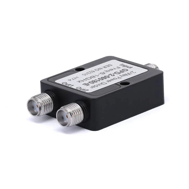
2 - Way Power Dividers
2 - Way Power Dividers are the simplest type of power dividers, used to split the input power into two equal or unequal parts. These dividers typically have relatively high efficiency compared to multi - way power dividers.
The design of 2 - way power dividers is relatively straightforward, which allows for better control of the insertion loss, isolation, and return loss. For example, a Wilkinson power divider, a commonly used 2 - way power divider, can achieve low insertion loss (typically less than 0.5 dB) and good isolation (greater than 20 dB) over a wide frequency range, resulting in high efficiency.
4 - Way Power Dividers
4 - Way Power Dividers are used when more output ports are required. However, as the number of output ports increases, the design becomes more complex, and the efficiency can be affected.

In a 4 - way power divider, the insertion loss is generally higher than that of a 2 - way power divider due to the increased complexity of the circuit and the longer transmission lines. Additionally, ensuring high isolation between the four output ports is more challenging, which can also lead to a decrease in efficiency. Nevertheless, with advanced design techniques and high - quality materials, modern 4 - way power dividers can still achieve reasonable efficiency levels.
16 - Way Power Dividers
16 - Way Power Dividers are used in applications where a large number of output ports are needed, such as in phased - array antennas. These power dividers face even greater challenges in terms of efficiency.
The high number of output ports requires a more complex circuit layout, which can result in increased insertion loss, lower isolation, and more difficult impedance matching. As a result, the efficiency of 16 - way power dividers is typically lower than that of 2 - way and 4 - way power dividers. However, through careful design and the use of advanced materials and manufacturing processes, it is possible to optimize the efficiency of 16 - way power dividers for specific applications.
Measuring and Improving Power Divider Efficiency
Measuring Efficiency
To measure the efficiency of a power divider, we typically use a network analyzer. The network analyzer can measure the insertion loss, return loss, and isolation of the power divider, which can then be used to calculate the efficiency.
First, the input power is measured at the input port of the power divider. Then, the power at each output port is measured. The total output power is calculated by summing up the power at all the output ports. The efficiency is then determined using the formula mentioned earlier.
Improving Efficiency
There are several ways to improve the efficiency of power dividers. One approach is to use high - quality materials with low resistance and low dielectric losses. For example, using a substrate material with a low loss tangent can significantly reduce the dielectric losses and improve the insertion loss.
Another way is to optimize the design of the power divider. This can include using proper impedance matching techniques, minimizing the length of the transmission lines, and improving the isolation between the output ports. Advanced simulation tools can be used to model and optimize the power divider design before fabrication.
Conclusion
The efficiency of power dividers is a critical parameter that affects the performance of RF and microwave systems. As a power divider supplier, we are committed to providing our customers with high - efficiency power dividers that meet their specific requirements.
Whether you need a 2 - Way Power Dividers, 4 - Way Power Dividers, or 16 - Way Power Dividers, we have the expertise and technology to deliver products with excellent efficiency. If you are interested in our power dividers or have any questions about power divider efficiency, please feel free to contact us for further discussion and procurement negotiation.
References
- Pozar, D. M. (2011). Microwave Engineering. Wiley.
- Matthaei, G. L., Young, L., & Jones, E. M. T. (1964). Microwave Filters, Impedance - Matching Networks, and Coupling Structures. McGraw - Hill.


