How do I improve the signal quality in a PCB connector?
Leave a message
In the realm of printed circuit board (PCB) design and manufacturing, ensuring optimal signal quality in PCB connectors is of paramount importance. As a seasoned PCB connectors supplier, I've witnessed firsthand the challenges that engineers and designers face when it comes to maintaining high - performance signal transmission. In this blog, I'll share some practical strategies and insights on how to improve the signal quality in a PCB connector.
Understanding the Basics of Signal Transmission in PCB Connectors
Before delving into the methods of improving signal quality, it's essential to understand how signals are transmitted through PCB connectors. A PCB connector serves as a bridge between different components on a PCB or between a PCB and an external device. Signals, whether they are electrical, optical, or radio - frequency (RF), travel through the connector's pins, contacts, and traces.
During this transmission, several factors can degrade the signal quality. These include impedance mismatches, electromagnetic interference (EMI), crosstalk, and signal attenuation. Impedance mismatch occurs when the impedance of the source, the transmission line, and the load are not properly matched. This can lead to signal reflections, which cause distortion and loss of signal integrity. EMI is the interference caused by external electromagnetic fields, which can introduce noise into the signal. Crosstalk is the unwanted coupling of signals between adjacent conductors, and signal attenuation is the loss of signal strength as it travels through the connector.
Selecting the Right Connector Type
One of the first steps in improving signal quality is selecting the appropriate connector type for your application. Different connector types have different electrical characteristics, and choosing the right one can significantly reduce signal degradation.
- Field Replaceable Connectors: These connectors are designed to be easily replaced in the field without the need for specialized tools or equipment. They are ideal for applications where connectors may need to be replaced due to wear and tear or damage. Field Replaceable Connectors offer flexibility and can be a great choice for ensuring long - term signal quality, especially in applications where maintenance is a concern.
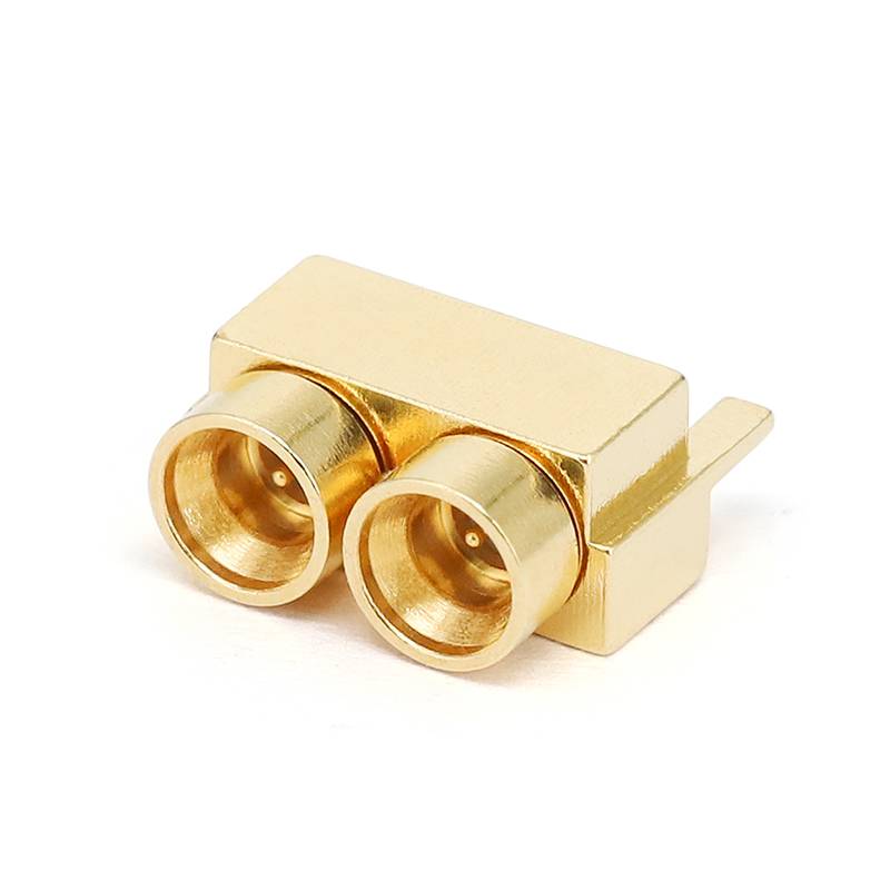
- Multi - coax Connectors: Multi - coax connectors are used for applications that require the transmission of multiple coaxial signals. They are designed to minimize crosstalk between the individual coaxial lines, which is crucial for maintaining signal integrity. Multi - coax Connectors are commonly used in high - speed data transmission and communication systems.
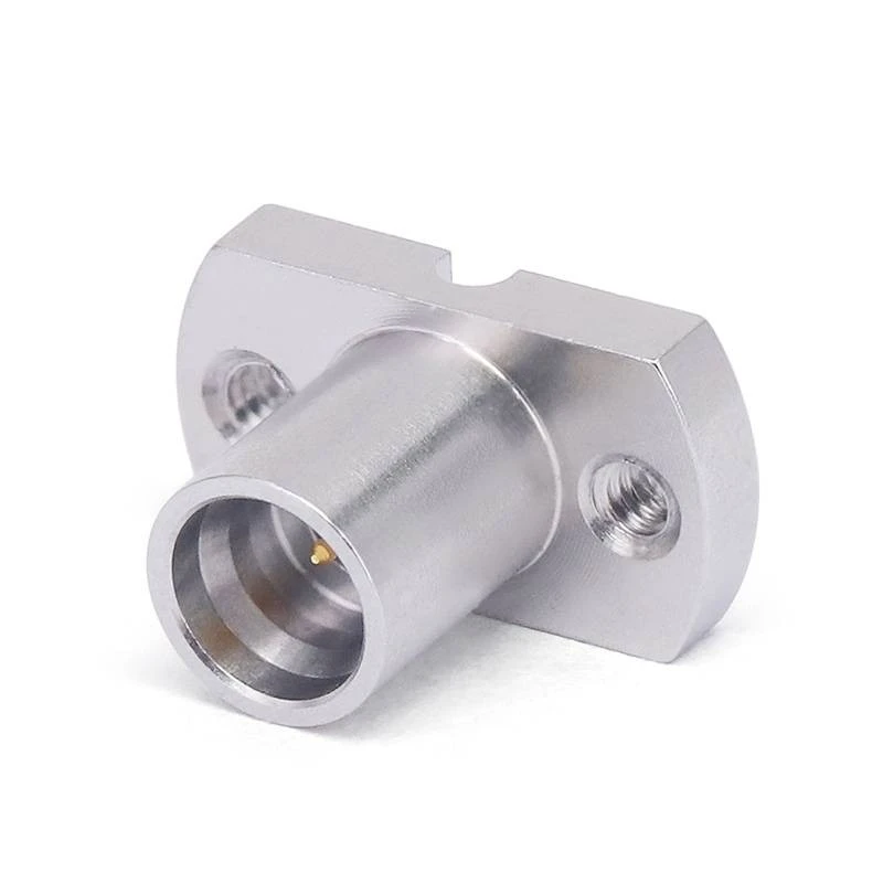
- Coax Connectors: Coaxial connectors are widely used for RF applications. They are designed to provide a low - loss transmission path for RF signals. Coax Connectors have a characteristic impedance that is carefully controlled to match the impedance of the coaxial cable and the RF device, which helps to minimize signal reflections.
Designing for Impedance Matching
Impedance matching is a critical factor in ensuring high - quality signal transmission. When the impedance of the source, the transmission line, and the load are not matched, signal reflections occur, which can lead to distortion and loss of signal strength.
To achieve impedance matching, the following steps can be taken:
- Proper Trace Design: The traces on the PCB should be designed with the correct width and thickness to achieve the desired characteristic impedance. The impedance of a trace is affected by its geometry, the dielectric constant of the PCB material, and the spacing between adjacent traces.
- Connector Selection: The connector should have an impedance that matches the impedance of the PCB traces and the external device. Many connectors are available with different impedance values, so it's important to choose the one that is appropriate for your application.
- Termination: Proper termination of the signal lines is essential for impedance matching. This can be achieved by using termination resistors at the end of the transmission line to absorb any reflected signals.
Minimizing Electromagnetic Interference (EMI)
EMI can have a significant impact on signal quality, especially in high - speed and high - frequency applications. To minimize EMI, the following techniques can be employed:
- Shielding: Using shielded connectors can help to reduce the amount of EMI that enters or exits the connector. Shielded connectors have a metal enclosure that surrounds the contacts, which acts as a Faraday cage to block external electromagnetic fields.
- Grounding: Proper grounding is crucial for reducing EMI. The connector should be connected to a low - impedance ground plane on the PCB to provide a path for the EMI currents to flow.
- Filtering: Adding filters to the signal lines can help to remove unwanted EMI frequencies. Filters can be in the form of capacitors, inductors, or ferrite beads, which are designed to attenuate specific frequencies.
Reducing Crosstalk
Crosstalk is the unwanted coupling of signals between adjacent conductors. It can cause interference and distortion in the signals, especially in high - density connector applications. To reduce crosstalk, the following methods can be used:
- Spacing: Increasing the spacing between adjacent conductors can reduce the coupling between them. This can be achieved by using wider traces or by increasing the pitch of the connector pins.
- Shielding: Similar to EMI reduction, shielding can also be used to reduce crosstalk. Shielded connectors or adding shielding between adjacent conductors can help to block the coupling of signals.
- Routing: Proper routing of the signal lines on the PCB can also help to reduce crosstalk. Avoiding parallel routing of adjacent signal lines and using orthogonal routing can minimize the coupling between them.
Controlling Signal Attenuation
Signal attenuation is the loss of signal strength as it travels through the connector. To control signal attenuation, the following steps can be taken:
- Material Selection: Using high - quality materials for the connector contacts and the PCB traces can help to reduce signal attenuation. Materials with low resistivity, such as copper, are commonly used for their excellent electrical conductivity.
- Length of the Transmission Line: Minimizing the length of the transmission line between the source and the load can reduce signal attenuation. This can be achieved by placing the connector as close as possible to the component or device it is connecting to.
- Frequency Considerations: Signal attenuation is frequency - dependent, with higher frequencies experiencing more attenuation than lower frequencies. In high - frequency applications, it's important to choose connectors and materials that are designed to minimize attenuation at the operating frequency.
Testing and Validation
Once the PCB connector has been designed and manufactured, it's important to test and validate its signal quality. This can be done using various testing equipment, such as network analyzers, oscilloscopes, and spectrum analyzers.
- S - Parameter Testing: S - parameter testing is a common method for measuring the electrical performance of a connector. It measures the scattering parameters of the connector, which include reflection coefficients, transmission coefficients, and crosstalk coefficients.
- Eye Diagram Testing: Eye diagram testing is used to evaluate the signal integrity of high - speed digital signals. It provides a visual representation of the signal quality, showing the opening of the eye, which indicates the amount of noise and jitter in the signal.
- EMI Testing: EMI testing is used to measure the amount of electromagnetic interference that is emitted by the connector. This is important for ensuring compliance with electromagnetic compatibility (EMC) standards.
Conclusion
Improving the signal quality in a PCB connector is a complex but achievable task. By selecting the right connector type, designing for impedance matching, minimizing EMI and crosstalk, controlling signal attenuation, and conducting thorough testing and validation, you can ensure that your PCB connector provides high - performance signal transmission.
As a PCB connectors supplier, we are committed to providing our customers with high - quality connectors that meet their specific requirements. If you are looking for a reliable partner for your PCB connector needs, we invite you to contact us for a detailed discussion about your project. Our team of experts is ready to assist you in selecting the right connector and implementing the best strategies for improving signal quality.
References
- Hall, Brian. "High - Speed Signal Propagation: Advanced Black Magic." Wiley - Interscience, 2009.
- Montrose, Mark I. "Printed Circuit Board Design Techniques for EMC Compliance: A Handbook for Designers." Wiley - Interscience, 2000.
- Johnson, Howard W., and Martin Graham. "High - Speed Digital Design: A Handbook of Black Magic." Prentice Hall, 1993.


